Introduction
The Machine Configuration module (hereinafter also referred to as MC or MConfig) is the core function of FAST. Here you can generate a TIA Portal project in the form of pre-connected xTypes. This is where the individual components such as the style guide design and the xType configuration(s) come together. It can be generated in an empty TIA Portal project or in an already existing TIA basic project. For this purpose, the project is read into the MC and can then be enriched with automatically generated code.
Open Machine Configuration
To open the MC module, first check whether you have set the correct TIA Portal version in FAST. Next, click the Machine Configuration tile in the Start menu.
Open FAST projects
To continue working on a project that has already been opened, you can reopen and edit it at any time.
- Click on one of the Open buttons
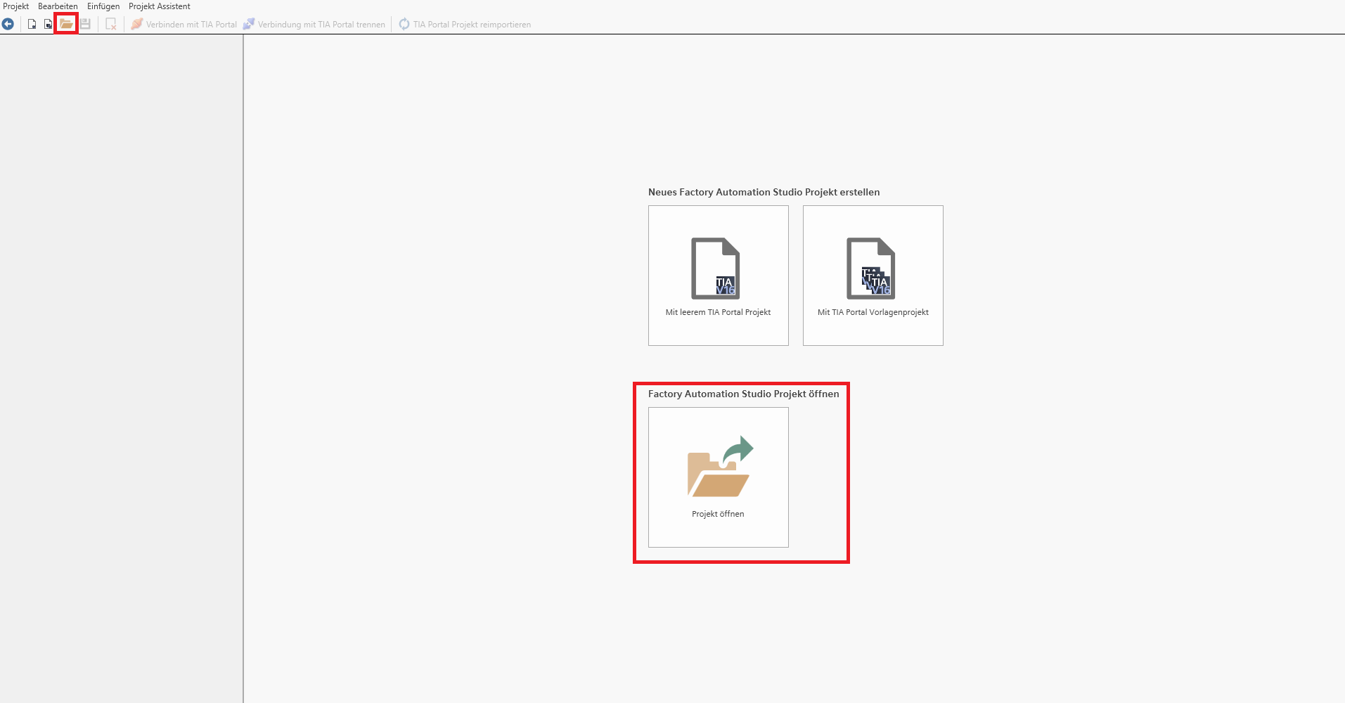
- Select the appropriate one from the file system *.apxx file. (xx=TIA version)

 The project file already contains the link to the associated style guide definition and the associated xType definition. If they are still in the same location in the file system where they were last saved, these files will be opened again. If the files have been moved or deleted, they must be relinked after opening the project.
Create new FAST project
There are 2 ways to create a new FAST project.
- Creating a new FAST project with a empty TIA Portal project. A new TIA Portal project is created here into which code can be generated. You can use this to quickly generate generated code to copy it manually into a target project, or to test the settings you have made, for example in the style guide.
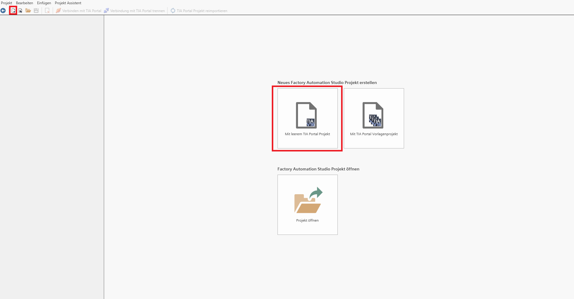
In the following dialog window, enter the libraries you want to use and the style guide definition. Choose a storage location for the new empty TIA project.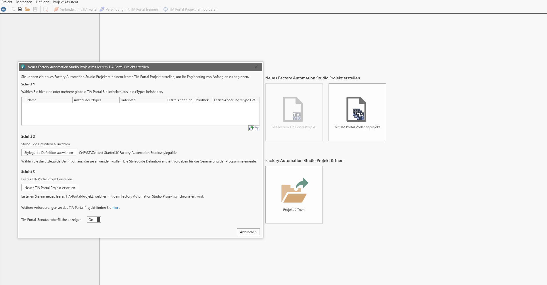
- Creating a new FAST project with a TIA template project. Here you use a standardized template project that can already include the hardware configuration and the symbol table. Furthermore, you can create the recurring part of the code (e.g. operating mode switching / basic functions, etc.) in the template project and use FAST to generate the variable part of the automation task.
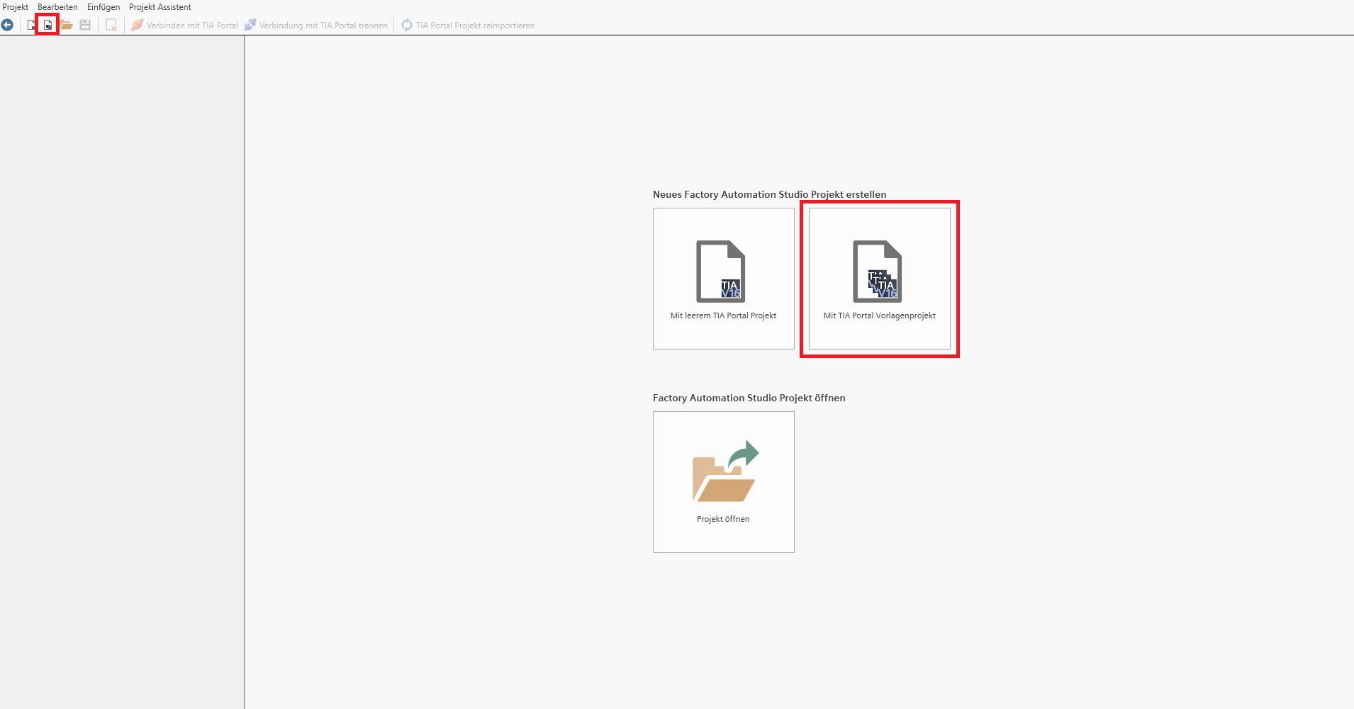
In the following dialog window, enter the libraries you want to use and the style guide definition. Select the storage location for the TIA template project to be used.
The project is now loaded into the TIA Portal and then the project is read into the Factory Automation Studio.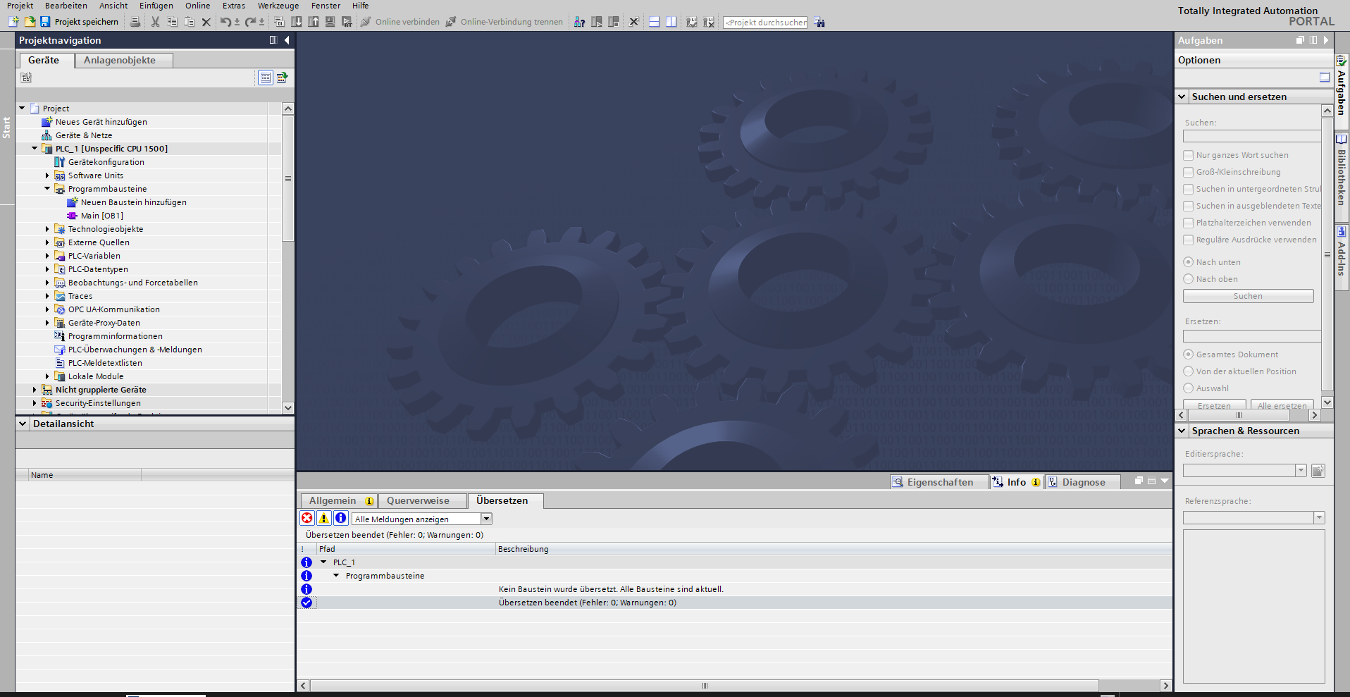
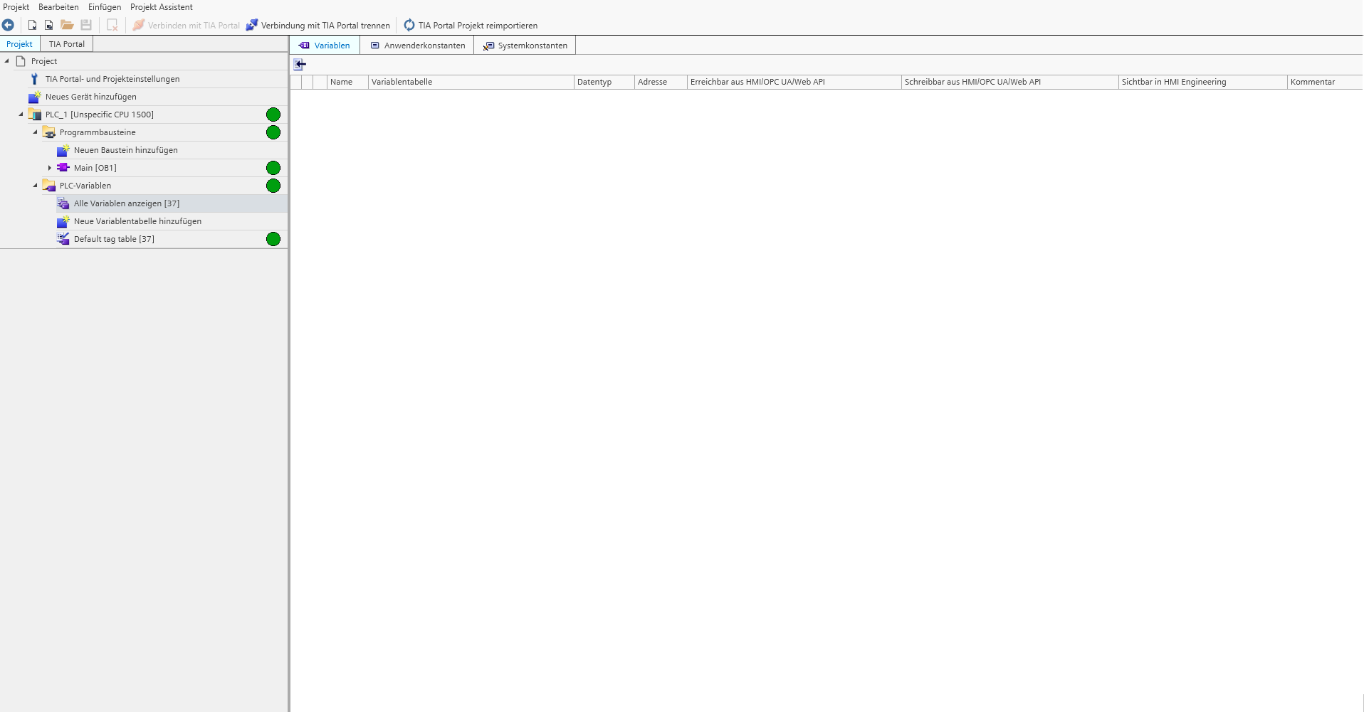
If the project has been completely imported, this is indicated by the green symbol in the project navigation. The project can now be edited without restrictions.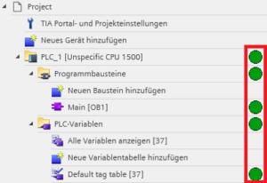
Overview of the Machine Configuration module
The MC module is divided into two areas. The project navigation area and the work area.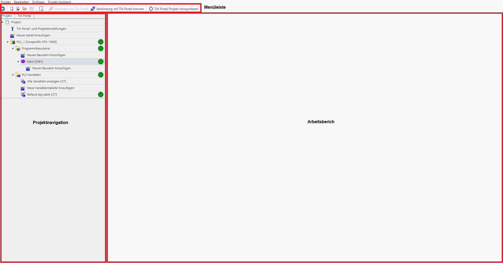
- menu bar
![]()
![]() back to the start menu
back to the start menu
![]() Create new FAST project with empty TIA project
Create new FAST project with empty TIA project
![]() Create new FAST project with template project
Create new FAST project with template project
![]() Open an already created FAST project
Open an already created FAST project
![]() Save change (FAST & TIA Portal)
Save change (FAST & TIA Portal)
![]() Delete selected object
Delete selected object
![]() Activate connection (openness) to the TIA Portal
Activate connection (openness) to the TIA Portal
![]() Deactivate connection (openness) to TIA Portal
Deactivate connection (openness) to TIA Portal
![]() Read back a manual change in the open TIA Portal project to FAST.
Read back a manual change in the open TIA Portal project to FAST.
- Project navigation
There are 2 views in the project navigation.
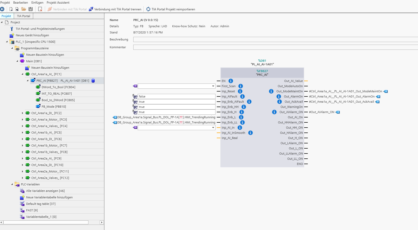
The Project view shows the TIA project at the call structure level. Here it is also possible to further edit individual xTypes that have already been generated manually afterwards.
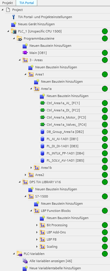
The TIA portal view shows the project in the group structure view.
Here it is possible to generate new structures in special target group folders.
- The workspace
A work area is available in the project view. Here it is possible to subsequently adjust the parameters of already generated xTypes. If a change is made, the corresponding xType in the TIA Portal project is deleted and regenerated. This function is only possible for xTypes whose wiring parameters have not been adjusted manually in the TIA Portal project.

No elements can be edited in the TIA portal view. It is only possible to display the contents of a DB.

Generate individual elements
- Generate individual blocks/xTypes in the project view
In the project view, individual xTypes can be generated based on the call structure. To do this, select the calling block and click on the “Add new block” icon below or select the function from the context menu with the right mouse button.

In the following user prompt, select the type and attributes of the block to be inserted. Depending on the type of the calling block, only the possible blocks are available for selection. If it is not possible to generate the object in the selected call structure, it is grayed out.
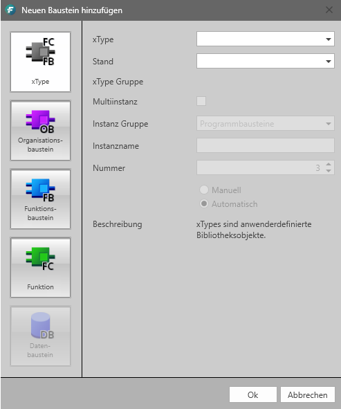
Select the type and version (xTypes only) of the block. If it is an FB, assign a unique instance DB name and a unique block number.
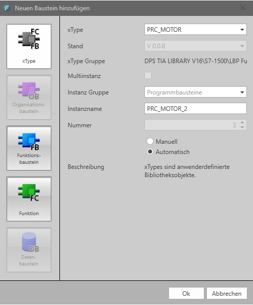
Click on ok to generate the block with the selected attributes 1x.
The block is displayed in the project view and generated in the TIA Portal.


Elements that have already been created can be renamed and/or deleted. For FBs, the instance name can be adjusted. The changes are implemented directly on the block in the TIA Portal.

 When subsequently changing objects, pay attention to whether they are already interconnected in the TIA Portal project. This can lead to inconsistencies in the TIA Portal project.
The active synchronization with the TIA Portal project is indicated by the green hourglass symbol on the right in the project navigation. Once the synchronization with the TIA Portal project is complete, the green symbol without an hourglass is displayed on the object again.
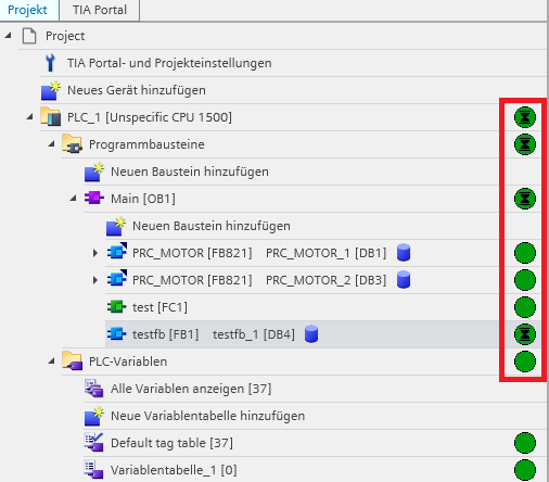
- Generating individual blocks/xTypes in the portal view
In the portal view, individual xTypes and building blocks can be generated based on the call structure and group folders. To do this, select the calling block or the corresponding group folder and click on the “Add new block” icon below or select the function from the context menu with the right mouse button.
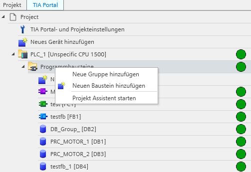
 If no calling block is selected, but a group folder, the new block/xType is only created in the TIA Portal but is not called.
In the following user prompt, select the type and attributes of the block to be inserted. Depending on the type of the calling block, only the possible blocks are available for selection. If it is not possible to generate the object in the selected call structure, it is grayed out.

Select the type and version (xTypes only) of the block. If it is an FB, assign a unique instance DB name and a unique block number.

Click on ok to generate the block with the selected attributes 1x.
The block is displayed in the project view and generated in the TIA Portal.


Elements that have already been created can be renamed and/or deleted. For FBs, the instance name can be adjusted. The changes are implemented directly on the block in the TIA Portal.

 When subsequently changing objects, pay attention to whether they are already interconnected in the TIA Portal project. This can lead to inconsistencies in the TIA Portal project.
Synchronizing with the TIA Portal project is indicated by the green hourglass symbol on the right in the project navigation. Once the synchronization with the TIA Portal project is complete, the green symbol without an hourglass is displayed on the object again.

- Generate individual group folders in the portal view
It is possible to generate individual group folders in the portal view. Here, new structures can be created or group folder structures already contained in the TIA Portal project can be expanded/changed.
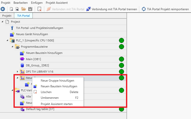
To create a new group folder, click on the target directory and right-click on the “Add new group” option in the context menu.
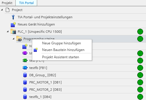
The group is created.
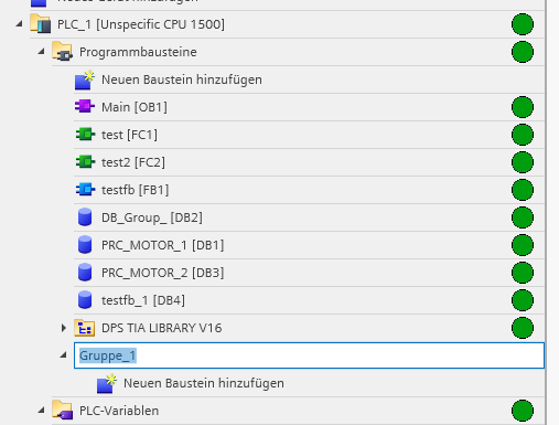
Now assign a unique group folder name. The group folder is automatically created in the TIA Portal project.
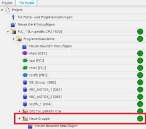
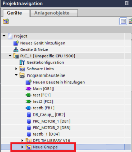
It is possible to rename or delete existing group folders afterwards. To do this, select the relevant folder and click on the desired action in the context menu. The TIA Portal project is automatically synchronized.

PLC variables import
It is possible to import PLC variable tables into the MConifg module or to create individual variable tables manually. PLC variable table-related group folders can also be created/changed.
There is no provision for creating and editing individual PLC tags.
The PLC variable tables are automatically synchronized with the TIA Portal project.
- Creating a new (empty) variable table
Click on the corresponding target directory and select the “Add new variable table” option in the context menu.

The variable table is created.

Assign a unique PLC tag table name.

The variable table is automatically synchronized in the TIA Portal project.
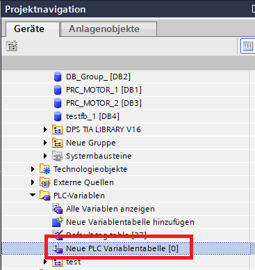
- Importing PLC tags
It is possible to import PLC tags into a specific PLC tag table or to create a new tag table during import. The source file must be one here *.sdf Be a file that corresponds to the TIA Portal import/export format of PLC variable tables.
To import a new variable table, click “Show all variables”. The contents of all variable tables are now displayed in the work area.
Click on the “Import” button.

An import window opens. Select the appropriate file from the file system. Only files with the extension *.sdf are permitted.
Click Import.
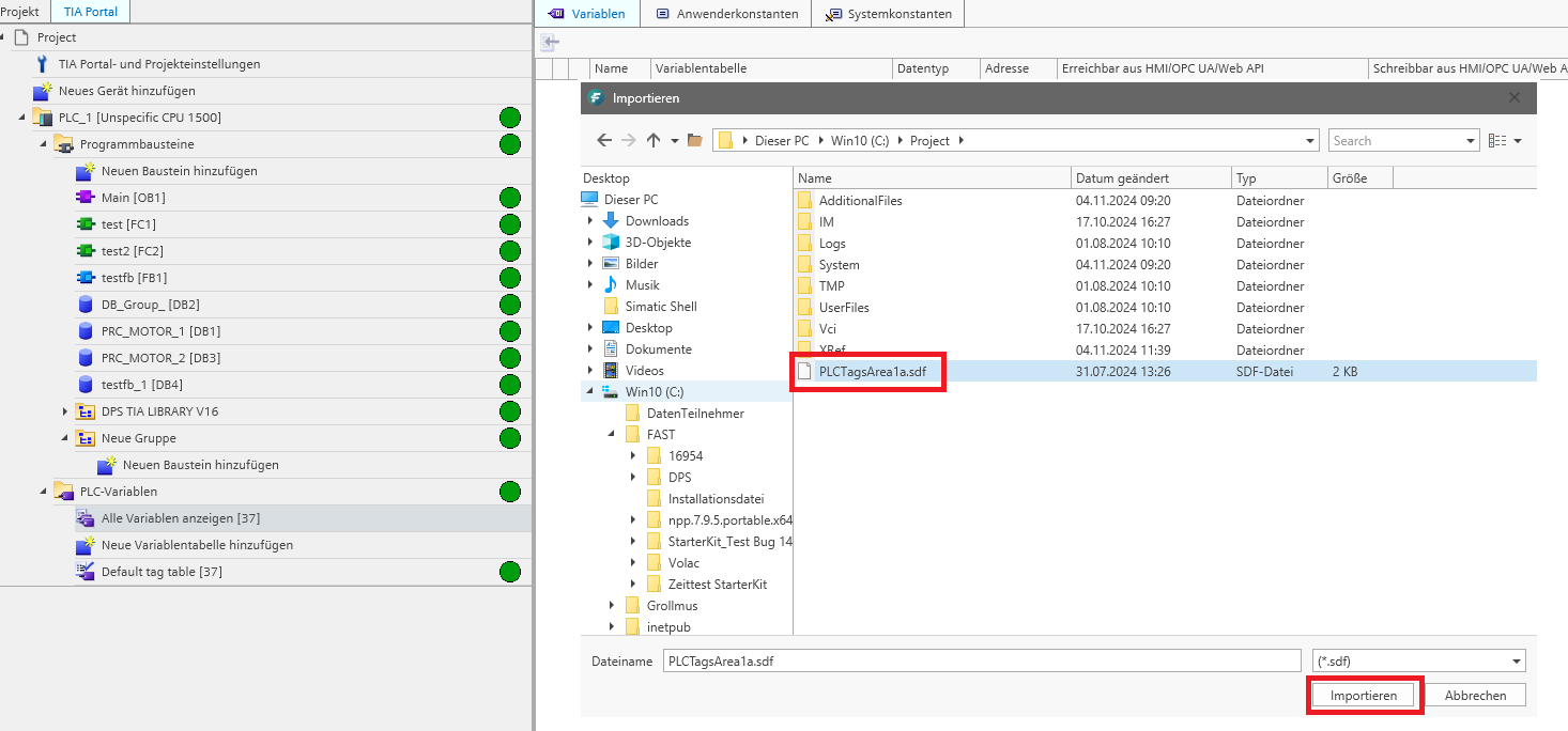
The variable table is now created (if it does not already exist) and the content is synchronized with the TIA Portal project.


Assign PLC variables manually
- Manually assigning PLC variables
In the project view you have the option of manually assigning existing variables. This can also happen on blocks that have already been generated. The already generated xType is deleted after the change and regenerated in the same place with the change. To do this, select the xType and click on the parameter you want to change in the work area. A drop-down menu appears with the PLC tags present in the project.

Select the corresponding PLC tag and confirm your entry with OK.

Assign PLC variables automatically
The Mconfig module offers the functionality to automatically assign PLC variables to the corresponding pre-connected parameters (input & output PLC variables). The function is based on the “Longest Common Substring” search algorithm. For this purpose, the PLC tag name and the PLC tag comment are searched and compared on the one hand and the parameter name and the parameter description on the xType instance DB name on the other side. The search is case sensitive.
In order to adapt the search algorithm, the number of hits and the quantity of search results can be set.
To start the automatic assignment, click Assign PLC variables in the context menu.
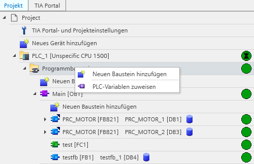
The search algorithm is now executed for the selected elements.
 In order to use the automated assignment of PLC tags, the search algorithm must be adapted to the project-specific circumstances and the correct function must be checked.
Please contact the software manufacturer in advance.
Overview of project assistant
The project assistant is the core function of the MConfig module. This makes it possible to generate masses of xTypes in a specific group folder. This can be done by manual configuration in the project assistant itself or by importing a preconfigured Excel file. This forms the interface between the FAST and other engineering tools.
- Open the project wizard
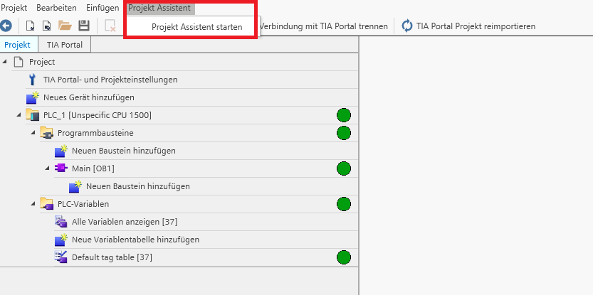
If you would like to generate in a specific group folder, you can also start the project assistant in the context menu of the folder. In this case, the target directory is already pre-assigned.
- Overview of project assistant
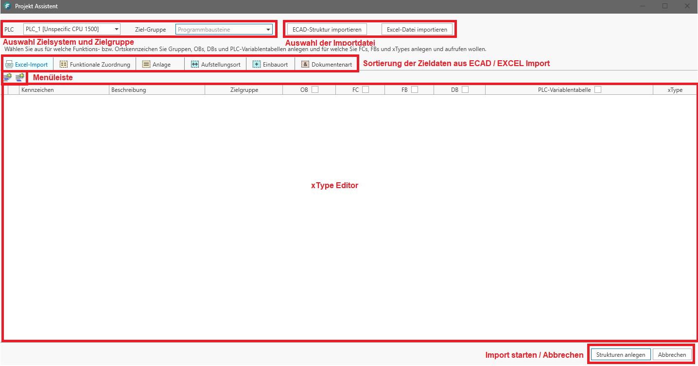
Excel import overview
The Excel import can be used to generate masses of xTypes with a wide variety of circuits. Depending on the configuration of the Excel file, it is also possible to generate its own group folder structure for each xType. The Excel file must meet the formatting requirements of the FAST Excel import. Please always use the included Excel template.
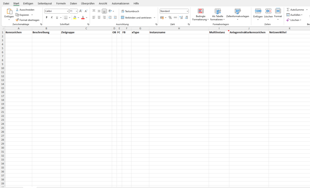
Description of columns:
- Mark: Name of the calling block that is checked in the OB/FC/FB column.
- Description:
- Target group: Group folder structure in which the xType should be generated. Example: Station1\Drives
- OB/FC/FB: Type of the calling block is generated based on the style guide guidelines and the content of the “Label” column if the corresponding line is marked with an “x”. The call to the xType is then implemented in this block.
- xType: Enter the exact xType name to be generated here. Make sure that this must also be found in the linked library.
- Instance name: If the xType is an FB, enter a unique instance name here.
- Multi-instance: If the calling block is an FB, the instance DB of the xType can optionally be created as a multi-instance. To do this, enter an “x” in the corresponding line.
- Plant identifier: The system identifier is used to generate tags for pre-connected networks as well as for the preliminary in-output tags.
- Network title: An individual network title for calling the xType can be entered here.
Working with the Excel import
In order to generate the contents of the Excel import file in the MC module, it must first be read in.
First check whether the PLC and target group are set correctly.
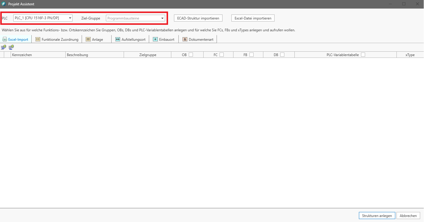
To do this, click on the “Import Excel file” button in the project assistant.
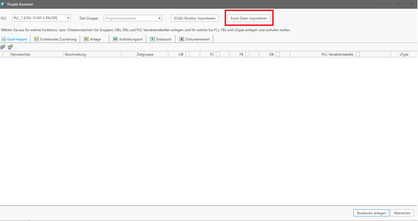
Select the corresponding *.xlsx file from the file system and click import.
The Excel file is read in.

If errors occur during the import, they are saved in a log file and can be viewed afterwards. If this is the case, a user prompt is displayed.
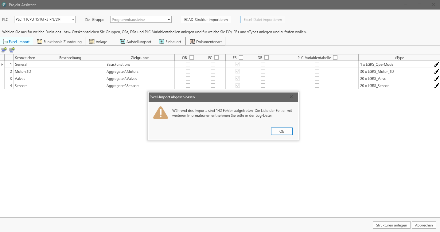
The log file directory opens automatically. Open the log file and evaluate the error message(s) and take appropriate action.

If the import process has been completed without errors, the imported xTypes are listed in the editor area of the project assistant.

Now check whether the individual entries are correct. If this is the case, you can start the generation process with the “Create structures” button.

The structures and xTypes are now synchronized in the TIA Portal project. The TIA Portal instance is blocked during this period and cannot be actively used.
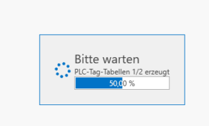
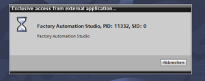
 The duration of generation depends on the complexity and the amount of xTypes to be generated and can take up to several minutes.
The process is finished when all objects are displayed with a green circle in the FAST portal view. The TIA Portal is released for manual editing again.
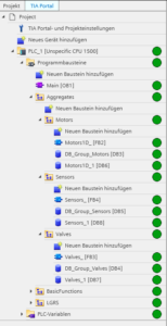
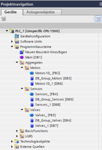
Finally, check whether the generated code in the TIA Portal project corresponds to the specifications from the Excel import file.

Edit ECAD structure
After reading the Excel import file, you have the opportunity to manually adjust the structure and the call parameters using the ECAD structure editor. To do this, after importing the Excel file, click on the pencil symbol at the end of each line.
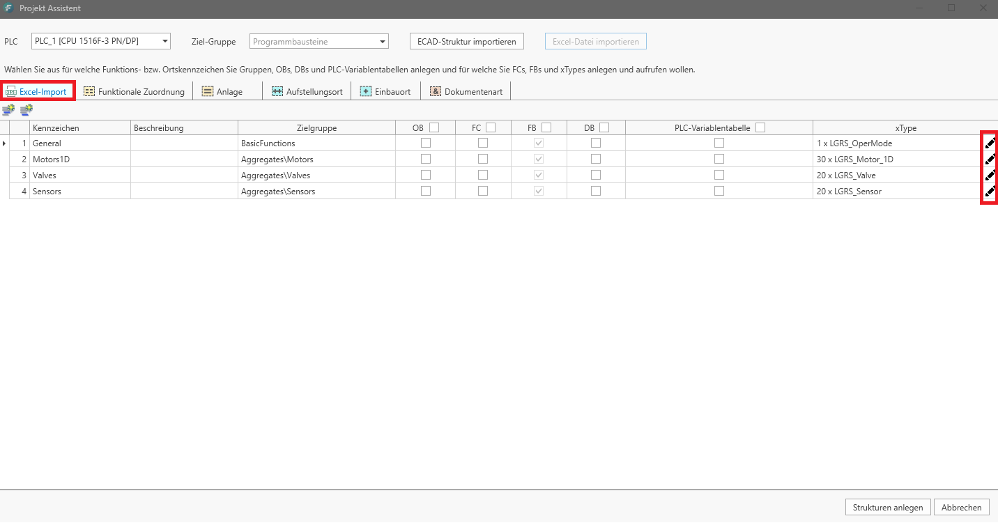
Another editor opens in which you have the option to manually adjust customizable parameters as well as the instance name and the network title to be generated.

menu bar
![]() Insert/add new line from marking
Insert/add new line from marking
![]() Automatically start PLC tag assignment for all xTypes in the list.
Automatically start PLC tag assignment for all xTypes in the list.
![]() Start automatic PLC tag assignment only for this instance.
Start automatic PLC tag assignment only for this instance.
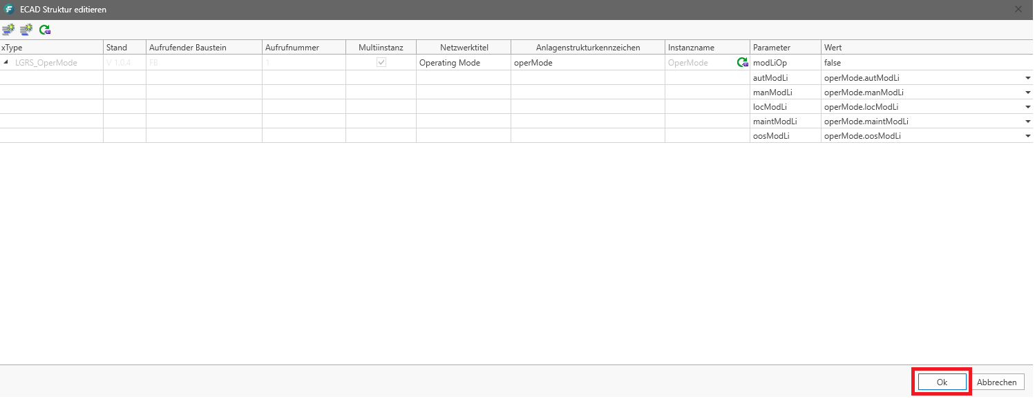
Confirm a change with the “OK” button. The editor is closed.
